(continued from Feature Diagram Overview, Part 1 )
The basic elements of a feature diagram are described below:
A concept or feature may have one or more mandatory features or sub-features, meaning every instance of a system contains the feature. Mandatory features are denoted with a filled circle at the end of the line relating the feature to the concept.

A concept or feature may also have one or more optional features which may or may not be included in any instance. Optional features are denoted with an open circle at the end of the line.

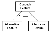
A concept or feature may have one or more sets of alternative features. In any system instance, one (and only one) feature from the set is included. An open arc between the feature lines denotes alternatives.

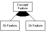
A concept or feature may have one or more features from a set of or-features. Any system instance has at least one of the features in the set. A filled arc between the features lines denotes or-features.

Alternative and or- features can be either mandatory or optional, as well. Because of the resulting semantics, certain relationships can be normalized out:

If one or more of the alternative features are optional, then all are optional alternatives.

If one or more of the or-features are optional, then all are optional features.
(concluded in Feature Diagram Overview, Part 3 )
______
This posting contributed to the following article:

how can two mandatory features be alternative to a feature?
If they are mandatory, both must be included.
If they are alternative, only one can be included
…???